
It's all in the details. Here are 6 Key Steps for the CAD/CAM file hand-off:
Our out-sourced CNC router and panel processing business grew out our willingness to cut the Plyboo, Richlite, and other panels we sell as raw material. Our pre-cut option is popular with installers and fabricators for interior millwork, counters and exterior rainscreens. However, most often we are cutting to an architect's specifications for a specialty job.
When it comes to CAD and CAM machining with CNC routers, one of the most common issues involves file conversion. Without care, CAD files, drawn during the architectural drafting and shop drawing phases do not efficiently convert into the tool pathing software, used to deliver files to a CNC router for machining. Follow some of these steadfast rules when preparing your files for a CNC programmer. These strategies ensure accuracy and drastically cut down on the back & forth that absorb time and resources for all parties.
These strategies ensure accuracy and drastically cut down on the back & forth that absorb time and resources for all parties:
- PAY ATTENTION TO SPACING
If the design includes perforations, you must take into account the material and its performance characteristics. Typically, most architectural panel materials need at least a ½” of spacing between cut-through perforations. Verify material tolerances and structural characteristics before starting your design to avoid time-consuming editing stages.
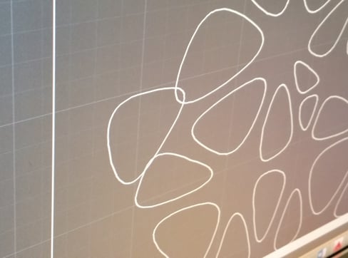
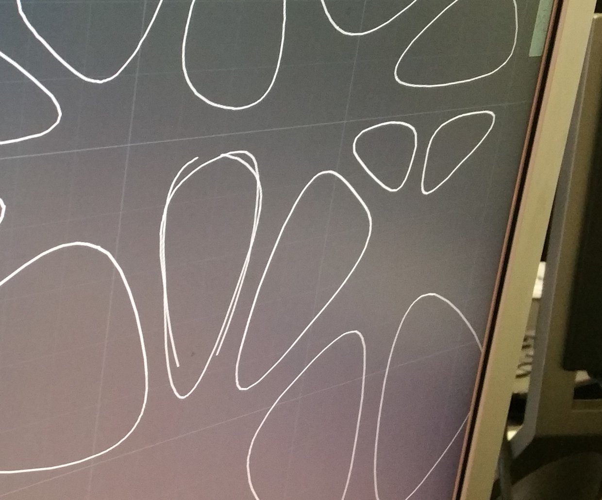
- TRIM OR REMOVE OVERLAPPING LINES
Trimming and removing overlapping lines reduces cost during the programming phase. We understand it’s typical during the design phase to have multiple versions and edits to a design. It becomes difficult to catch small revisions, especially drawings with multiple layers and a lot of detail. Completing a final, detailed review to “clean up” your drawing before submitting files to a programmer saves a lot of time and money during the programming stages. Our programmers never want to change the design intent, so these items usually warrant a call back to the designer. It saves money but also your time.
- ACCOUNT FOR TOOLING KERF’s
You must consider tooling when designing, especially with inside corners, irregular geometry, and spacing. Typically, ¼” diameter tooling is the smallest diameter used. This will yield an 1/8” radius on all inside corners. Also, similar to a saw blade eating up an eighth inch “kerf”, router bits at a minimum cut a path the width of the diameter of the tooling.
- CLOSE OBJECTSMake sure your geometry is “Closed” and/or a poly-line. Tool pathing software used in CNC programming cannot read open lines or geometries. Review your drawing and convert all open shapes to "Closed". It’s a good habit when designing for CNC work to draw in poly-lines.
- SCALE YOUR MATERIAL
Consider the size of the material and scale your drawing accordingly. When we machine or cut a 60" x 144" or 48x96 Richlite panel, we can’t use that whole size, even if the panels are a bit oversized. Size your design allowing for a ½” offset around the perimeter, a 48" x 96" panel becoming a 47" x 95". Incorporating this space allows for a cleanup pass, where the CNC router head comes back along the outline of the shape and takes just a few thousandths of an inch off the edge, making for a smooth surface. This saves a lot of time in post-processing operations, in many cases eliminating manual deburring or hand sanding altogether.
- SAVING - FILE FORMATS
Save your design in .DXF and .DWG file formats. These formats communicate well with most CAD/CAM software. DXF and DWG and are also easy to edit. Section drawings are extremely helpful when there are multiple depths of cut.
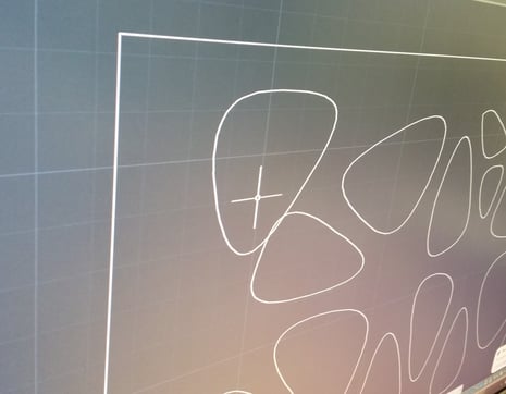
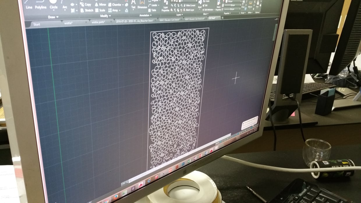
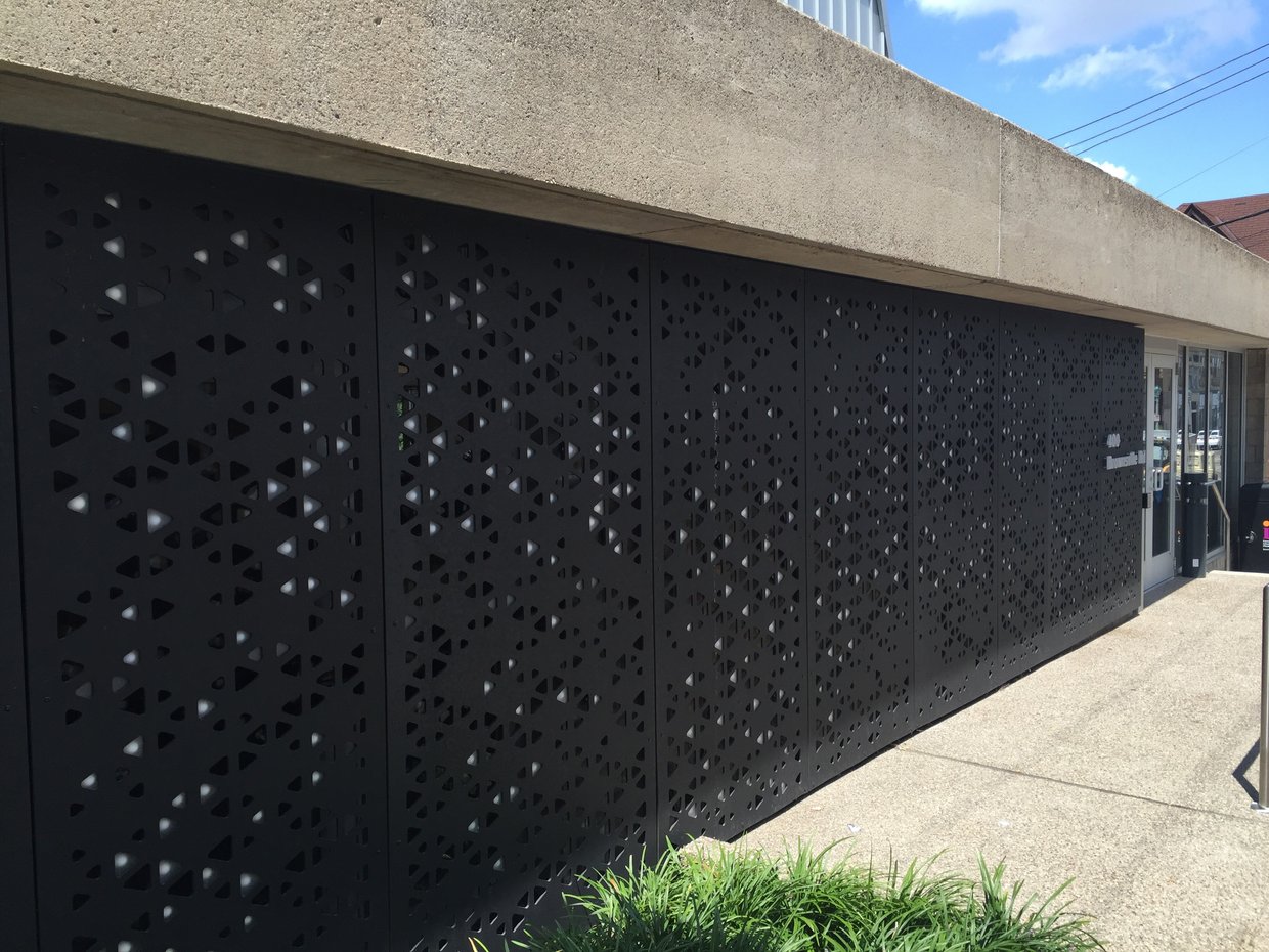
Pulling back, the scope of the work gets overwhelming. The hours of re-drawing start to pile up with multiple panels. Below is an example of a recent project involving a pattern series of multiple cut-through perforations. The design included a running sequence of panels with rounded egg-like shapes. It’s a lovely design aesthetically, but upon closer look, the design revealed several execution issues, needing multiple hours drawing to clean it up enough to program.
The end results were beautiful with the black wall panels contrasting with the concrete, the holes in the Richlite panels breaking up the otherwise monolithic surface.
For our Richlite CNC routing instructions click here.

